EE589 Final August 23.2014 Name ____________________________________ Student ID __________________
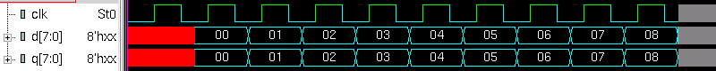
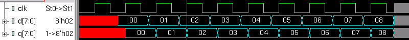
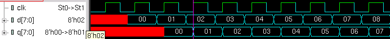
1.1 Which waveform is the simulation result of Verilog code below?
module dut
(
input clk,
input [7:0] d,
output logic [7:0] q
);
always @(posedge clk)
q <= d;
endmodule
1.2 Which waveform is the simulation result of Verilog code below?
module dut
(
input clk,
input [7:0] d,
output logic [7:0] q
);
logic [7:0] r;
always @(posedge clk)
begin
r <= d;
q <= r;
end
endmodule
1.3 Which waveform is the simulation result of Verilog code below?
module dut
(
input clk,
input [7:0] d,
output logic [7:0] q
);
always @*
q = d;
endmodule
1.4 Which waveform is the simulation result of Verilog code below?
module dut
(
input clk,
input [7:0] d,
output logic [7:0] q
);
logic [7:0] r;
always @(posedge clk)
r <= d;
always @(posedge clk)
q <= r;
endmodule
1.5 Which waveform is the simulation result of Verilog code below?
module dut
(
input clk,
input [7:0] d,
output logic [7:0] q
);
logic [7:0] r;
always @(posedge clk)
begin
r = d;
q <= r;
end
endmodule
module testbench;
logic clk;
logic [7:0] d, q;
dut dut (clk, d, q);
initial
begin
clk = 0;
forever
#10 clk = ! clk;
end
initial
begin
$dumpvars ();
for (int i = 0; i < 10; i++)
begin
@(posedge clk);
#15;
d = i;
end
$finish;
end
endmodule
a)
 b)
b)
 c)
c)
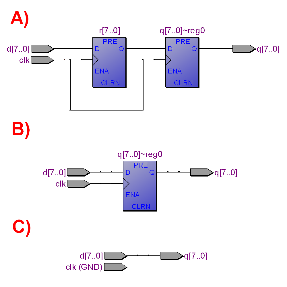
 2.1 What schematics correspond to Verilog code below?
module dut
(
input clk,
input [7:0] d,
output logic [7:0] q
);
logic [7:0] r;
always @(posedge clk)
r <= d;
always @(posedge clk)
q <= r;
endmodule
2.2 What schematics correspond to Verilog code below?
module dut
(
input clk,
input [7:0] d,
output logic [7:0] q
);
always @(posedge clk)
q <= d;
endmodule
2.3 What schematics correspond to Verilog code below?
module dut
(
input clk,
input [7:0] d,
output logic [7:0] q
);
logic [7:0] r;
always @(posedge clk)
begin
r <= d;
q <= r;
end
endmodule
2.4 What schematics correspond to Verilog code below?
module dut
(
input clk,
input [7:0] d,
output logic [7:0] q
);
always @*
q = d;
endmodule
2.5 What schematics correspond to Verilog code below?
module dut
(
input clk,
input [7:0] d,
output logic [7:0] q
);
logic [7:0] r;
always @(posedge clk)
begin
r = d;
q <= r;
end
endmodule
2.1 What schematics correspond to Verilog code below?
module dut
(
input clk,
input [7:0] d,
output logic [7:0] q
);
logic [7:0] r;
always @(posedge clk)
r <= d;
always @(posedge clk)
q <= r;
endmodule
2.2 What schematics correspond to Verilog code below?
module dut
(
input clk,
input [7:0] d,
output logic [7:0] q
);
always @(posedge clk)
q <= d;
endmodule
2.3 What schematics correspond to Verilog code below?
module dut
(
input clk,
input [7:0] d,
output logic [7:0] q
);
logic [7:0] r;
always @(posedge clk)
begin
r <= d;
q <= r;
end
endmodule
2.4 What schematics correspond to Verilog code below?
module dut
(
input clk,
input [7:0] d,
output logic [7:0] q
);
always @*
q = d;
endmodule
2.5 What schematics correspond to Verilog code below?
module dut
(
input clk,
input [7:0] d,
output logic [7:0] q
);
logic [7:0] r;
always @(posedge clk)
begin
r = d;
q <= r;
end
endmodule
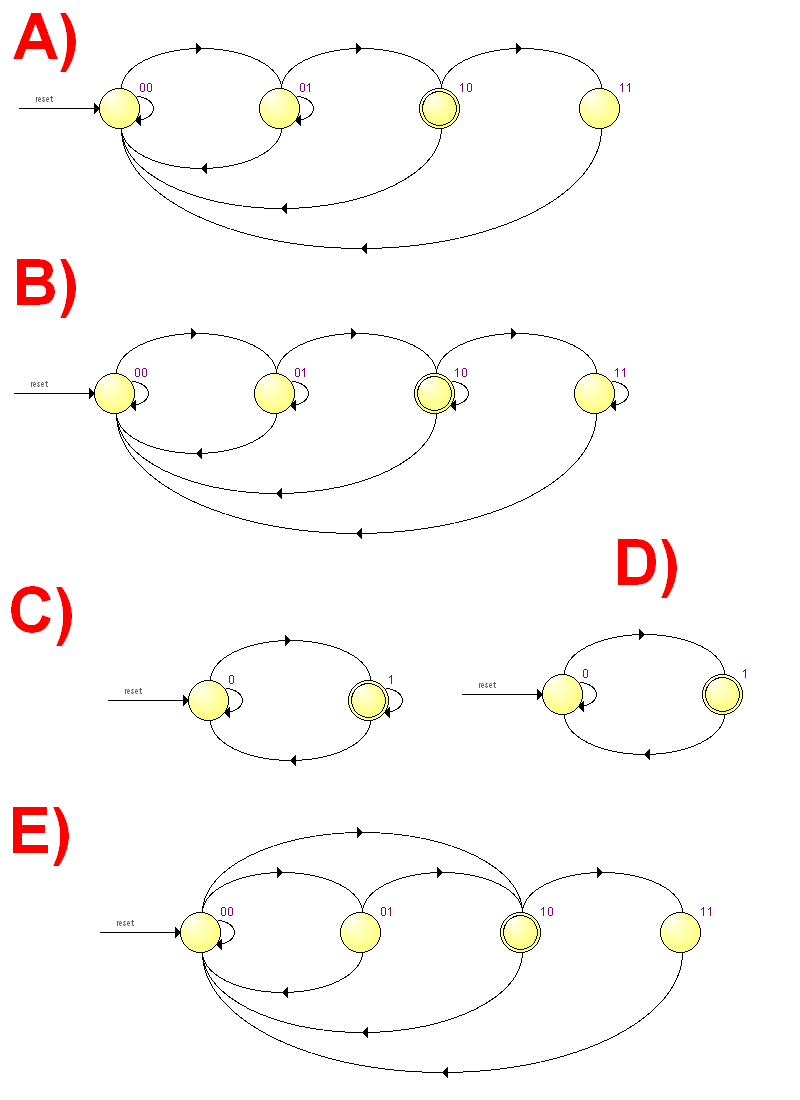
 3.1 What Finite State Machine (FSM) state diagram correspond to Verilog code below?
module dut
(
input clk,
input resetn,
input a,
output b
);
logic [1:0] state;
always @(posedge clk)
if (! resetn)
state <= 0;
else
case (state)
0: if ( a) state <= 1;
1: if (! a) state <= 2;
2: state <= 3;
3: state <= 0;
endcase
assign b = (state == 2);
endmodule
3.2 What Finite State Machine (FSM) state diagram correspond to Verilog code below?
module dut
(
input clk,
input resetn,
input a,
output b
);
logic [1:0] state;
always @(posedge clk)
if (! resetn)
state <= 0;
else
case (state)
0: state <= a ? 1 : 2;
1: state <= 2;
2: state <= 3;
3: state <= 0;
endcase
assign b = (state == 2);
endmodule
3.3 What Finite State Machine (FSM) state diagram correspond to Verilog code below?
module dut
(
input clk,
input resetn,
input a,
output b
);
logic [1:0] state;
always @(posedge clk)
if (! resetn)
state <= 0;
else
case (state)
0: if ( a) state <= 1;
1: if (! a) state <= 2;
2: if ( a) state <= 3;
3: if (! a) state <= 0;
endcase
assign b = (state == 2);
endmodule
3.4 What Finite State Machine (FSM) state diagram correspond to Verilog code below?
module dut
(
input clk,
input resetn,
input a,
output b
);
logic state;
always @(posedge clk)
if (! resetn)
state <= 0;
else
case (state)
0: if ( a) state <= 1;
1: if (! a) state <= 0;
endcase
assign b = (state == 1);
endmodule
3.5 What Finite State Machine (FSM) state diagram correspond to Verilog code below?
module dut
(
input clk,
input resetn,
input a,
output b
);
logic [0:0] state;
always @(posedge clk)
if (! resetn)
state <= 0;
else
case (state)
0: state <= 1;
1: state <= 0;
endcase
assign b = (state == 1);
endmodule
3.1 What Finite State Machine (FSM) state diagram correspond to Verilog code below?
module dut
(
input clk,
input resetn,
input a,
output b
);
logic [1:0] state;
always @(posedge clk)
if (! resetn)
state <= 0;
else
case (state)
0: if ( a) state <= 1;
1: if (! a) state <= 2;
2: state <= 3;
3: state <= 0;
endcase
assign b = (state == 2);
endmodule
3.2 What Finite State Machine (FSM) state diagram correspond to Verilog code below?
module dut
(
input clk,
input resetn,
input a,
output b
);
logic [1:0] state;
always @(posedge clk)
if (! resetn)
state <= 0;
else
case (state)
0: state <= a ? 1 : 2;
1: state <= 2;
2: state <= 3;
3: state <= 0;
endcase
assign b = (state == 2);
endmodule
3.3 What Finite State Machine (FSM) state diagram correspond to Verilog code below?
module dut
(
input clk,
input resetn,
input a,
output b
);
logic [1:0] state;
always @(posedge clk)
if (! resetn)
state <= 0;
else
case (state)
0: if ( a) state <= 1;
1: if (! a) state <= 2;
2: if ( a) state <= 3;
3: if (! a) state <= 0;
endcase
assign b = (state == 2);
endmodule
3.4 What Finite State Machine (FSM) state diagram correspond to Verilog code below?
module dut
(
input clk,
input resetn,
input a,
output b
);
logic state;
always @(posedge clk)
if (! resetn)
state <= 0;
else
case (state)
0: if ( a) state <= 1;
1: if (! a) state <= 0;
endcase
assign b = (state == 1);
endmodule
3.5 What Finite State Machine (FSM) state diagram correspond to Verilog code below?
module dut
(
input clk,
input resetn,
input a,
output b
);
logic [0:0] state;
always @(posedge clk)
if (! resetn)
state <= 0;
else
case (state)
0: state <= 1;
1: state <= 0;
endcase
assign b = (state == 1);
endmodule
 4.1 What MIPS assembly code corresponds to the following C code?
int e;
void f (int a, int b, int mask)
{
e = (a & mask) | (b & ~ mask);
}
4.2 What MIPS assembly code corresponds to the following C code?
int f (int n)
{
if (n == 0)
return 1;
else
return n * f (n - 1);
}
4.3 What MIPS assembly code corresponds to the following C code?
int f (int a, int b)
{
int i, sum;
for (i = a; i <= b; i++)
sum += i;
return sum;
}
4.4 What MIPS assembly code corresponds to the following C code?
int a [10];
int f ()
{
int i, sum;
for (i = 0; i < 10; i++)
sum += a [i];
return sum;
}
4.5 What MIPS assembly code corresponds to the following C code?
int a, b;
int f (int state)
{
int next_state;
switch (state)
{
case 0: if (a) next_state = 1; break;
case 1: if (b) next_state = 2; break;
case 2: next_state = 0; break;
}
return next_state;
}
////////// a //////////
f:
li $3,1
beq $4,$3,.L3
li $3,2
beq $4,$3,.L6
nop
bne $4,$0,.L9
nop
lw $2,%gp_rel(a)($28)
j $31
sltu $2,$0,$2
.L3:
li $2,2
lw $3,%gp_rel(b)($28)
j $31
movz $2,$0,$3
.L6:
move $2,$0
.L9:
j $31
nop
////////// b //////////
f:
addiu $sp,$sp,-24
sw $31,20($sp)
sw $16,16($sp)
move $16,$4
beq $4,$0,.L2
li $2,1
jal f
addiu $4,$4,-1
mul $2,$2,$16
.L2:
lw $31,20($sp)
lw $16,16($sp)
j $31
addiu $sp,$sp,24
////////// c //////////
f:
slt $3,$5,$4
bne $3,$0,.L5
nop
addu $2,$2,$4
.L4:
addiu $4,$4,1
slt $3,$5,$4
beq $3,$0,.L4
addu $2,$2,$4
subu $2,$2,$4
.L5:
j $31
nop
////////// d //////////
f:
nor $2,$0,$6
and $5,$2,$5
and $4,$4,$6
or $2,$5,$4
j $31
sw $2,%gp_rel(e)($28)
////////// e //////////
f:
lui $3,%hi(a)
addiu $3,$3,%lo(a)
addiu $5,$3,40
.L3:
lw $4,0($3)
addiu $3,$3,4
bne $3,$5,.L3
addu $2,$2,$4
j $31
nop
///////////////////////
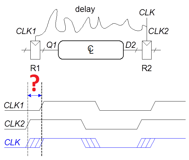
5.1 What kind of delay is illustrated on the picture below (marked by "?")?
a) Propagation delay: tpd = max delay from input to output
b) Contamination delay: tcd = min delay from input to output
c) Skew: difference between two clock edges. The clock doesn�t arrive at all registers at same time.
4.1 What MIPS assembly code corresponds to the following C code?
int e;
void f (int a, int b, int mask)
{
e = (a & mask) | (b & ~ mask);
}
4.2 What MIPS assembly code corresponds to the following C code?
int f (int n)
{
if (n == 0)
return 1;
else
return n * f (n - 1);
}
4.3 What MIPS assembly code corresponds to the following C code?
int f (int a, int b)
{
int i, sum;
for (i = a; i <= b; i++)
sum += i;
return sum;
}
4.4 What MIPS assembly code corresponds to the following C code?
int a [10];
int f ()
{
int i, sum;
for (i = 0; i < 10; i++)
sum += a [i];
return sum;
}
4.5 What MIPS assembly code corresponds to the following C code?
int a, b;
int f (int state)
{
int next_state;
switch (state)
{
case 0: if (a) next_state = 1; break;
case 1: if (b) next_state = 2; break;
case 2: next_state = 0; break;
}
return next_state;
}
////////// a //////////
f:
li $3,1
beq $4,$3,.L3
li $3,2
beq $4,$3,.L6
nop
bne $4,$0,.L9
nop
lw $2,%gp_rel(a)($28)
j $31
sltu $2,$0,$2
.L3:
li $2,2
lw $3,%gp_rel(b)($28)
j $31
movz $2,$0,$3
.L6:
move $2,$0
.L9:
j $31
nop
////////// b //////////
f:
addiu $sp,$sp,-24
sw $31,20($sp)
sw $16,16($sp)
move $16,$4
beq $4,$0,.L2
li $2,1
jal f
addiu $4,$4,-1
mul $2,$2,$16
.L2:
lw $31,20($sp)
lw $16,16($sp)
j $31
addiu $sp,$sp,24
////////// c //////////
f:
slt $3,$5,$4
bne $3,$0,.L5
nop
addu $2,$2,$4
.L4:
addiu $4,$4,1
slt $3,$5,$4
beq $3,$0,.L4
addu $2,$2,$4
subu $2,$2,$4
.L5:
j $31
nop
////////// d //////////
f:
nor $2,$0,$6
and $5,$2,$5
and $4,$4,$6
or $2,$5,$4
j $31
sw $2,%gp_rel(e)($28)
////////// e //////////
f:
lui $3,%hi(a)
addiu $3,$3,%lo(a)
addiu $5,$3,40
.L3:
lw $4,0($3)
addiu $3,$3,4
bne $3,$5,.L3
addu $2,$2,$4
j $31
nop
///////////////////////
5.1 What kind of delay is illustrated on the picture below (marked by "?")?
a) Propagation delay: tpd = max delay from input to output
b) Contamination delay: tcd = min delay from input to output
c) Skew: difference between two clock edges. The clock doesn�t arrive at all registers at same time.
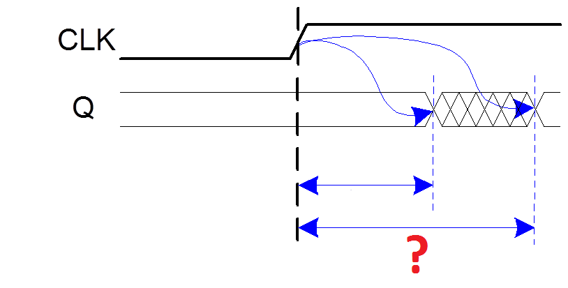
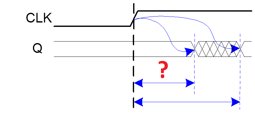
 5.2 What kind of delay is illustrated on the picture below (marked by "?")?
a) Clock-to-Q Propagation delay:
tpcq = time after clock edge that the output Q is guaranteed to be stable (i.e., to stop changing)
b) Clock-to-Q Contamination delay:
tccq = time after clock edge that Q might be unstable (i.e., start changing)
c) Skew: difference between two clock edges. The clock doesn�t arrive at all registers at same time
5.2 What kind of delay is illustrated on the picture below (marked by "?")?
a) Clock-to-Q Propagation delay:
tpcq = time after clock edge that the output Q is guaranteed to be stable (i.e., to stop changing)
b) Clock-to-Q Contamination delay:
tccq = time after clock edge that Q might be unstable (i.e., start changing)
c) Skew: difference between two clock edges. The clock doesn�t arrive at all registers at same time
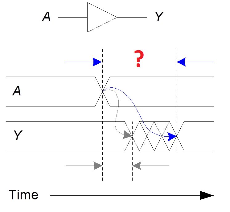
 5.3 What kind of delay is illustrated on the picture below (marked by "?")?
a) Propagation delay: tpd = max delay from input to output
b) Contamination delay: tcd = min delay from input to output
c) Skew: difference between two clock edges. The clock doesn�t arrive at all registers at same time
5.3 What kind of delay is illustrated on the picture below (marked by "?")?
a) Propagation delay: tpd = max delay from input to output
b) Contamination delay: tcd = min delay from input to output
c) Skew: difference between two clock edges. The clock doesn�t arrive at all registers at same time
 5.4 What kind of delay is illustrated on the picture below (marked by "?")?
a) Clock-to-Q Propagation delay:
tpcq = time after clock edge that the output Q is guaranteed to be stable (i.e., to stop changing)
b) Clock-to-Q Contamination delay:
tccq = time after clock edge that Q might be unstable (i.e., start changing)
c) Skew: difference between two clock edges. The clock doesn�t arrive at all registers at same time.
5.4 What kind of delay is illustrated on the picture below (marked by "?")?
a) Clock-to-Q Propagation delay:
tpcq = time after clock edge that the output Q is guaranteed to be stable (i.e., to stop changing)
b) Clock-to-Q Contamination delay:
tccq = time after clock edge that Q might be unstable (i.e., start changing)
c) Skew: difference between two clock edges. The clock doesn�t arrive at all registers at same time.
 5.5 What kind of delay is illustrated on the picture below (marked by "?")?
a) Propagation delay: tpd = max delay from input to output
b) Contamination delay: tcd = min delay from input to output
c) Skew: difference between two clock edges. The clock doesn�t arrive at all registers at same time.
5.5 What kind of delay is illustrated on the picture below (marked by "?")?
a) Propagation delay: tpd = max delay from input to output
b) Contamination delay: tcd = min delay from input to output
c) Skew: difference between two clock edges. The clock doesn�t arrive at all registers at same time.
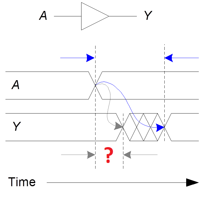
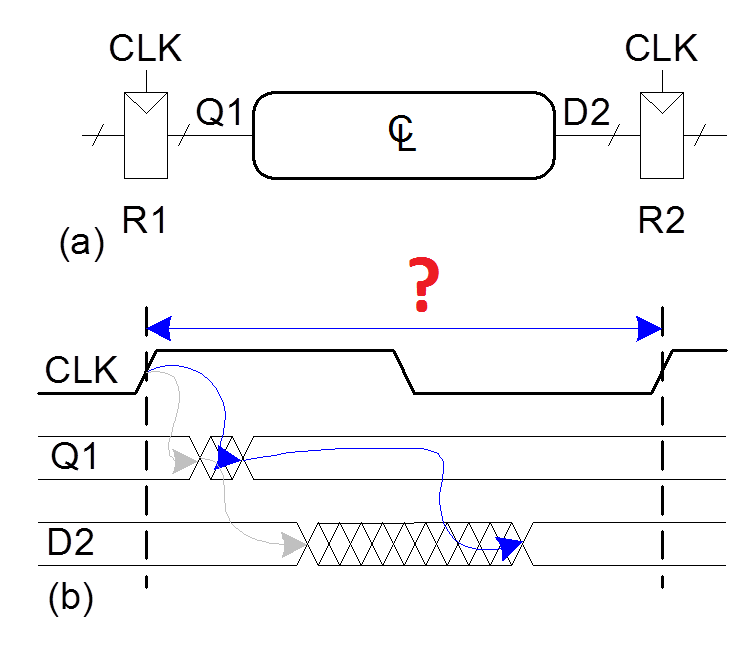
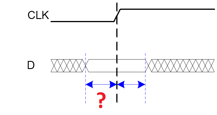
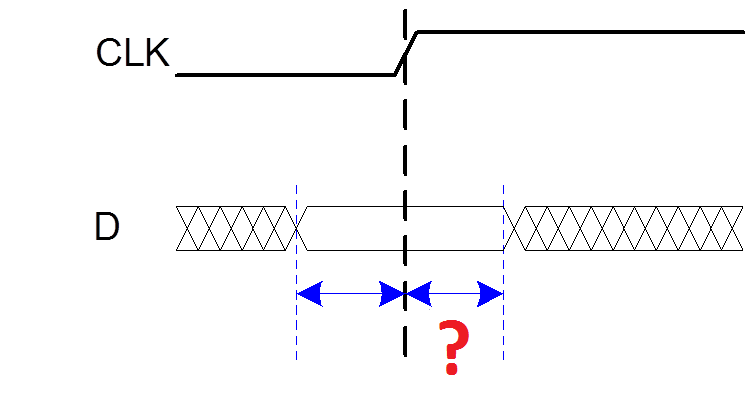
 6.1 What kind of timing constraint is illustrated on the picture below (marked by "?")?
a) Setup time: tsetup = time before clock edge data must be stable (i.e. not changing)
b) Hold time: thold = time after clock edge data must be stable
c) Aperture time: ta = time around clock edge data must be stable (ta = tsetup + thold)
d) Tc = minimum and maximum delays between registers
6.1 What kind of timing constraint is illustrated on the picture below (marked by "?")?
a) Setup time: tsetup = time before clock edge data must be stable (i.e. not changing)
b) Hold time: thold = time after clock edge data must be stable
c) Aperture time: ta = time around clock edge data must be stable (ta = tsetup + thold)
d) Tc = minimum and maximum delays between registers
 6.2 What kind of timing constraint is illustrated on the picture below (marked by "?")?
a) Setup time: tsetup = time before clock edge data must be stable (i.e. not changing)
b) Hold time: thold = time after clock edge data must be stable
c) Aperture time: ta = time around clock edge data must be stable (ta = tsetup + thold)
d) Tc = minimum and maximum delays between registers
6.2 What kind of timing constraint is illustrated on the picture below (marked by "?")?
a) Setup time: tsetup = time before clock edge data must be stable (i.e. not changing)
b) Hold time: thold = time after clock edge data must be stable
c) Aperture time: ta = time around clock edge data must be stable (ta = tsetup + thold)
d) Tc = minimum and maximum delays between registers
 6.3 What kind of timing constraint is illustrated on the picture below (marked by "?")?
a) Setup time: tsetup = time before clock edge data must be stable (i.e. not changing)
b) Hold time: thold = time after clock edge data must be stable
c) Aperture time: ta = time around clock edge data must be stable (ta = tsetup + thold)
d) Tc = minimum and maximum delays between registers
6.3 What kind of timing constraint is illustrated on the picture below (marked by "?")?
a) Setup time: tsetup = time before clock edge data must be stable (i.e. not changing)
b) Hold time: thold = time after clock edge data must be stable
c) Aperture time: ta = time around clock edge data must be stable (ta = tsetup + thold)
d) Tc = minimum and maximum delays between registers
 6.4 What kind of timing constraint is illustrated on the picture below (marked by "?")?
a) Setup time: tsetup = time before clock edge data must be stable (i.e. not changing)
b) Hold time: thold = time after clock edge data must be stable
c) Aperture time: ta = time around clock edge data must be stable (ta = tsetup + thold)
d) Tc = minimum and maximum delays between registers
6.4 What kind of timing constraint is illustrated on the picture below (marked by "?")?
a) Setup time: tsetup = time before clock edge data must be stable (i.e. not changing)
b) Hold time: thold = time after clock edge data must be stable
c) Aperture time: ta = time around clock edge data must be stable (ta = tsetup + thold)
d) Tc = minimum and maximum delays between registers
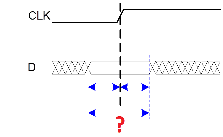
 6.5 What kind of timing constraint is illustrated on the picture below (marked by "?")?
a) Setup time: tsetup = time before clock edge data must be stable (i.e. not changing)
b) Hold time: thold = time after clock edge data must be stable
c) Aperture time: ta = time around clock edge data must be stable (ta = tsetup + thold)
d) Tc = minimum and maximum delays between registers
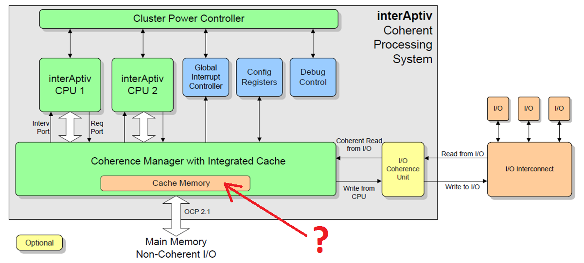
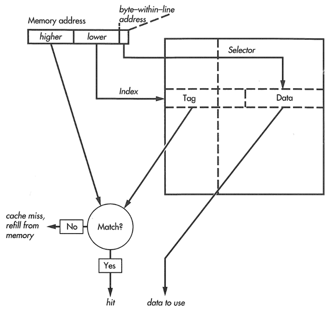
7.1 What kind of cache is likely to be shown on the picture (marked by "?")?
a) Direct L1 cache
b) Two-way L1 cache
c) L2 cache
6.5 What kind of timing constraint is illustrated on the picture below (marked by "?")?
a) Setup time: tsetup = time before clock edge data must be stable (i.e. not changing)
b) Hold time: thold = time after clock edge data must be stable
c) Aperture time: ta = time around clock edge data must be stable (ta = tsetup + thold)
d) Tc = minimum and maximum delays between registers
7.1 What kind of cache is likely to be shown on the picture (marked by "?")?
a) Direct L1 cache
b) Two-way L1 cache
c) L2 cache
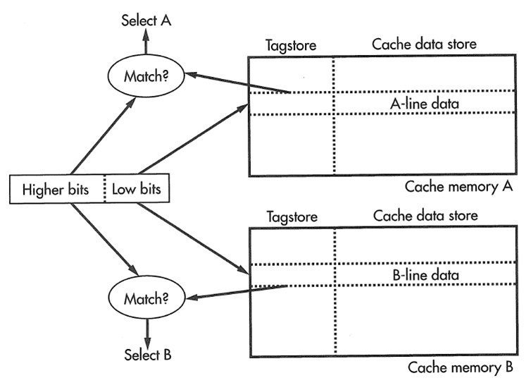
 7.2 What kind of cache is shown on the picture?
a) Fully associative cache
b) Direct cache
c) Two-way cache
7.2 What kind of cache is shown on the picture?
a) Fully associative cache
b) Direct cache
c) Two-way cache
 7.3 What kind of cache is shown on the picture?
a) Fully associative cache
b) Direct cache
c) Two-way cache
7.3 What kind of cache is shown on the picture?
a) Fully associative cache
b) Direct cache
c) Two-way cache
 7.4 What kind of cache is likely to be shown on the picture (marked by "?")?
a) Direct L1 cache
b) Two-way L1 cache
c) L2 cache
7.5 What kind of cache is shown on the picture?
a) Fully associative cache
b) Direct cache
c) Two-way cache
8.1 Encode MIPS instruction
sll $8, $9, 4
a) 00084902
b) 00084903
c) 00094100
d) 00094102
e) 00094103
8.2 Encode MIPS instruction
srl $8, $9, 4
a) 00084902
b) 00084903
c) 00094100
d) 00094102
e) 00094103
8.3 Encode MIPS instruction
sra $8, $9, 4
a) 00084902
b) 00084903
c) 00094100
d) 00094102
e) 00094103
8.4 Encode MIPS instruction
srl $9, $8, 4
a) 00084902
b) 00084903
c) 00094100
d) 00094102
e) 00094103
8.5 Encode MIPS instruction
sra $9, $8, 4
a) 00084902
b) 00084903
c) 00094100
d) 00094102
e) 00094103
9.1 Disassemble MIPS instruction
01084025
a) sltu $10, $9, $8
b) bltz $8, 1f
c) lb $8, ($8)
d) srav $9, $8, $10
e) or $8, $8, $8
9.2 Disassemble MIPS instruction
0128502B
a) sltu $10, $9, $8
b) bltz $8, 1f
c) lb $8, ($8)
d) srav $9, $8, $10
e) or $8, $8, $8
9.3 Disassemble MIPS instruction
01484807
a) sltu $10, $9, $8
b) bltz $8, 1f
c) lb $8, ($8)
d) srav $9, $8, $10
e) or $8, $8, $8
9.4 Disassemble MIPS instruction
05000002
a) sltu $10, $9, $8
b) bltz $8, 1f
c) lb $8, ($8)
d) srav $9, $8, $10
e) or $8, $8, $8
9.5 Disassemble MIPS instruction
81080000
a) sltu $10, $9, $8
b) bltz $8, 1f
c) lb $8, ($8)
d) srav $9, $8, $10
e) or $8, $8, $8
10.1 What is the result of the following MIPS program execution?
li $8, 12
li $9, 13
li $10, 14
addu $8, $9, $10
a) $8=0x0000000c, $9=0x0000000d, $10=00000019
b) $8=0x0000000c, $9=0x0000001a, $10=0000000e
c) $8=0x00000014, $9=0x00000012, $10=00000019
d) $8=0x0000001b, $9=0x0000000d, $10=0000000e
e) $8=0x0000000c, $9=0x0000001a, $10=0000000e
10.2 What is the result of the following MIPS program execution?
li $8, 12
li $9, 13
li $10, 14
addu $9, $10, $8
a) $8=0x0000000c, $9=0x0000000d, $10=00000019
b) $8=0x0000000c, $9=0x0000001a, $10=0000000e
c) $8=0x00000014, $9=0x00000012, $10=00000019
d) $8=0x0000001b, $9=0x0000000d, $10=0000000e
e) $8=0x0000000c, $9=0x0000001a, $10=0000000e
10.3 What is the result of the following MIPS program execution?
li $8, 12
li $9, 13
li $10, 14
addu $10, $8, $9
a) $8=0x0000000c, $9=0x0000000d, $10=00000019
b) $8=0x0000000c, $9=0x0000001a, $10=0000000e
c) $8=0x00000014, $9=0x00000012, $10=00000019
d) $8=0x0000001b, $9=0x0000000d, $10=0000000e
e) $8=0x0000000c, $9=0x0000001a, $10=0000000e
10.4 What is the result of the following MIPS program execution?
li $8, 12
li $9, 13
li $10, 14
addu $9, $8, $10
a) $8=0x0000000c, $9=0x0000000d, $10=00000019
b) $8=0x0000000c, $9=0x0000001a, $10=0000000e
c) $8=0x00000014, $9=0x00000012, $10=00000019
d) $8=0x0000001b, $9=0x0000000d, $10=0000000e
e) $8=0x0000000c, $9=0x0000001a, $10=0000000e
10.5 What is the result of the following MIPS program execution?
li $8, 12
li $9, 13
li $10, 14
addu $10, $9, $8
a) $8=0x0000000c, $9=0x0000000d, $10=00000019
b) $8=0x0000000c, $9=0x0000001a, $10=0000000e
c) $8=0x00000014, $9=0x00000012, $10=00000019
d) $8=0x0000001b, $9=0x0000000d, $10=0000000e
e) $8=0x0000000c, $9=0x0000001a, $10=0000000e
11.1 Which rule for signal assignment is violated in the following code?
a) Synchronous sequential logic: use always @(posedge clk) or always_ff @(posedge clk)
and nonblocking assignments (<=)
always_ff @ (posedge clk)
q <= d; // nonblocking
b) Simple combinational logic: use continuous assignments (assign�)
assign y = a & b;
c) More complicated combinational logic: use always @* or always_comb and blocking assignments (=)
d) Assign a signal in only one always statement or continuous assignment statement
e) This code does not violate any rules for signal assignment
module dut
(
input clk,
input [7:0] d,
output logic [7:0] q
);
logic [7:0] r;
always @(posedge clk)
r = d;
always @(posedge clk)
q = r;
endmodule
11.2 Which rule for signal assignment is violated in the following code?
a) Synchronous sequential logic: use always @(posedge clk) or always_ff @(posedge clk)
and nonblocking assignments (<=)
always_ff @ (posedge clk)
q <= d; // nonblocking
b) Simple combinational logic: use continuous assignments (assign�)
assign y = a & b;
c) More complicated combinational logic: use always @* or always_comb and blocking assignments (=)
d) Assign a signal in only one always statement or continuous assignment statement
e) This code does not violate any rules for signal assignment
module dut
(
input clk,
input [7:0] d,
output logic [7:0] q
);
always @(posedge clk)
if (d == 3)
q <= 4;
always @(posedge clk)
if (d == 7)
q <= 1;
endmodule
11.3 Which rule for signal assignment is violated in the following code?
a) Synchronous sequential logic: use always @(posedge clk) or always_ff @(posedge clk)
and nonblocking assignments (<=)
always_ff @ (posedge clk)
q <= d; // nonblocking
b) Simple combinational logic: use continuous assignments (assign�)
assign y = a & b;
c) More complicated combinational logic: use always @* or always_comb and blocking assignments (=)
d) Assign a signal in only one always statement or continuous assignment statement
e) This code does not violate any rules for signal assignment
module isqrt
(
input clock,
input reset_n,
input run,
input [31:0] x,
output reg ready,
output reg [15:0] y
);
reg [31:0] m, r_m;
reg [31:0] tx, r_tx;
reg [31:0] ty, r_ty;
reg [31:0] b, r_b;
reg new_ready;
always @*
begin
if (run)
begin
m = 31'h4000_0000;
tx = x;
ty = 0;
end
else
begin
m = r_m;
tx = r_tx;
ty = r_ty;
end
b = ty | m;
ty = ty >> 1;
if (tx >= b)
begin
tx = tx - b;
ty = ty | m;
end
new_ready = m [0];
m = m >> 2;
end
always @(posedge clock or negedge reset_n)
begin
if (! reset_n)
begin
ready <= 0;
y <= 0;
end
else if (new_ready)
begin
ready <= 1;
y <= ty [15:0];
end
else
begin
ready <= 0;
r_m <= m;
r_tx <= tx;
r_ty <= ty;
r_b <= b;
end
end
endmodule
11.4 Which rule for signal assignment is violated in the following code?
a) Synchronous sequential logic: use always @(posedge clk) or always_ff @(posedge clk)
and nonblocking assignments (<=)
always_ff @ (posedge clk)
q <= d; // nonblocking
b) Simple combinational logic: use continuous assignments (assign�)
assign y = a & b;
c) More complicated combinational logic: use always @* or always_comb and blocking assignments (=)
d) Assign a signal in only one always statement or continuous assignment statement
e) This code does not violate any rules for signal assignment
module isqrt
(
input clock,
input reset_n,
input run,
input [31:0] x,
output reg ready,
output reg [15:0] y
);
reg [31:0] m, r_m;
reg [31:0] tx, r_tx;
reg [31:0] ty, r_ty;
reg [31:0] b, r_b;
reg new_ready;
always @*
begin
if (run)
begin
m = 31'h4000_0000;
tx = x;
ty = 0;
end
else
begin
m = r_m;
tx = r_tx;
ty = r_ty;
end
b = ty | m;
ty = ty >> 1;
if (tx >= b)
begin
tx = tx - b;
ty = ty | m;
end
new_ready = m [0];
m = m >> 2;
end
always @(posedge clock or negedge reset_n)
begin
if (! reset_n)
begin
ready = 0;
y = 0;
end
else if (new_ready)
begin
ready = 1;
y = ty [15:0];
end
else
begin
ready = 0;
r_m = m;
r_tx = tx;
r_ty = ty;
r_b = b;
end
end
endmodule
11.5 Which rule for signal assignment is violated in the following code?
a) Synchronous sequential logic: use always @(posedge clk) or always_ff @(posedge clk)
and nonblocking assignments (<=)
always_ff @ (posedge clk)
q <= d; // nonblocking
b) Simple combinational logic: use continuous assignments (assign�)
assign y = a & b;
c) More complicated combinational logic: use always @* or always_comb and blocking assignments (=)
d) Assign a signal in only one always statement or continuous assignment statement
e) This code does not violate any rules for signal assignment
module isqrt
(
input clock,
input reset_n,
input run,
input [31:0] x,
output reg ready,
output reg [15:0] y
);
reg [31:0] m, r_m;
reg [31:0] tx, r_tx;
reg [31:0] ty, r_ty;
reg [31:0] b, r_b;
reg new_ready;
always @*
begin
if (run)
begin
m <= 31'h4000_0000;
tx <= x;
ty <= 0;
end
else
begin
m <= r_m;
tx <= r_tx;
ty <= r_ty;
end
b <= ty | m;
ty <= ty >> 1;
if (tx >= b)
begin
tx <= tx - b;
ty <= ty | m;
end
new_ready <= m [0];
m <= m >> 2;
end
always @(posedge clock or negedge reset_n)
begin
if (! reset_n)
begin
ready <= 0;
y <= 0;
end
else if (new_ready)
begin
ready <= 1;
y <= ty [15:0];
end
else
begin
ready <= 0;
r_m <= m;
r_tx <= tx;
r_ty <= ty;
r_b <= b;
end
end
endmodule
12.1 Suppose you are using the following module
to generate low-frequency clock using 5 MHz clock.
What will be the resulting frequencies
of clock_for_debouncing and clock_for_display?
12.2 Suppose you are using the following module
to generate low-frequency clock using 50 MHz clock.
What will be the resulting frequencies
of clock_for_debouncing and clock_for_display?
12.3 Suppose you are using the following module
to generate low-frequency clock using 8 MHz clock.
What will be the resulting frequencies
of clock_for_debouncing and clock_for_display?
12.4 Suppose you are using the following module
to generate low-frequency clock using 80 MHz clock.
What will be the resulting frequencies
of clock_for_debouncing and clock_for_display?
12.5 Suppose you are using the following module
to generate low-frequency clock using 50 MHz clock.
What will be the resulting frequencies
of clock_for_debouncing and clock_for_display?
a) 153 Hz and 2441 Hz
b) 15.3 Hz and 244.1 Hz
c) 1.53 Hz and 24.41 Hz
d) 95.4 Hz and 1525 Hz
e) 9.54 Hz and 152.5 Hz
module clock_divider
(
input clock,
input reset,
output clock_for_debouncing,
output clock_for_display
);
reg [19:0] counter;
always @(posedge clock)
begin
if (reset)
counter <= 0;
else
counter <= counter + 1;
end
assign clock_for_debouncing = counter [19];
assign clock_for_display = counter [15];
endmodule
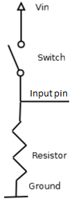
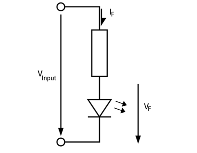
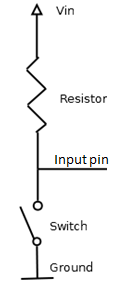
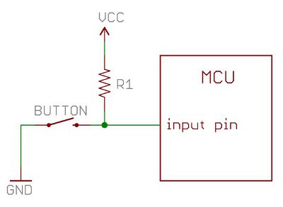
13.1 What is the function of the resistor in this particular circuit?
a) To protect LED from excessive current
b) Pullup - to provide the default value 1 for the input
c) Pulldown - to provide the default value 0 for the input
d) All the above
e) This resistor does not have any function in this circuit
13.2 What is the function of the resistor in this particular circuit?
a) To protect LED from excessive current
b) Pullup - to provide the default value 1 for the input
c) Pulldown - to provide the default value 0 for the input
d) All the above
e) This resistor does not have any function in this circuit
13.3 What is the function of the resistor in this particular circuit?
a) To protect LED from excessive current
b) Pullup - to provide the default value 1 for the input
c) Pulldown - to provide the default value 0 for the input
d) All the above
e) This resistor does not have any function in this circuit
13.4 What is the function of the resistor in this particular circuit?
a) To protect LED from excessive current
b) Pullup - to provide the default value 1 for the input
c) Pulldown - to provide the default value 0 for the input
d) All the above
e) This resistor does not have any function in this circuit
13.5 What is the function of the resistor in this particular circuit?
a) To protect LED from excessive current
b) Pullup - to provide the default value 1 for the input
c) Pulldown - to provide the default value 0 for the input
d) All the above
e) This resistor does not have any function in this circuit
7.4 What kind of cache is likely to be shown on the picture (marked by "?")?
a) Direct L1 cache
b) Two-way L1 cache
c) L2 cache
7.5 What kind of cache is shown on the picture?
a) Fully associative cache
b) Direct cache
c) Two-way cache
8.1 Encode MIPS instruction
sll $8, $9, 4
a) 00084902
b) 00084903
c) 00094100
d) 00094102
e) 00094103
8.2 Encode MIPS instruction
srl $8, $9, 4
a) 00084902
b) 00084903
c) 00094100
d) 00094102
e) 00094103
8.3 Encode MIPS instruction
sra $8, $9, 4
a) 00084902
b) 00084903
c) 00094100
d) 00094102
e) 00094103
8.4 Encode MIPS instruction
srl $9, $8, 4
a) 00084902
b) 00084903
c) 00094100
d) 00094102
e) 00094103
8.5 Encode MIPS instruction
sra $9, $8, 4
a) 00084902
b) 00084903
c) 00094100
d) 00094102
e) 00094103
9.1 Disassemble MIPS instruction
01084025
a) sltu $10, $9, $8
b) bltz $8, 1f
c) lb $8, ($8)
d) srav $9, $8, $10
e) or $8, $8, $8
9.2 Disassemble MIPS instruction
0128502B
a) sltu $10, $9, $8
b) bltz $8, 1f
c) lb $8, ($8)
d) srav $9, $8, $10
e) or $8, $8, $8
9.3 Disassemble MIPS instruction
01484807
a) sltu $10, $9, $8
b) bltz $8, 1f
c) lb $8, ($8)
d) srav $9, $8, $10
e) or $8, $8, $8
9.4 Disassemble MIPS instruction
05000002
a) sltu $10, $9, $8
b) bltz $8, 1f
c) lb $8, ($8)
d) srav $9, $8, $10
e) or $8, $8, $8
9.5 Disassemble MIPS instruction
81080000
a) sltu $10, $9, $8
b) bltz $8, 1f
c) lb $8, ($8)
d) srav $9, $8, $10
e) or $8, $8, $8
10.1 What is the result of the following MIPS program execution?
li $8, 12
li $9, 13
li $10, 14
addu $8, $9, $10
a) $8=0x0000000c, $9=0x0000000d, $10=00000019
b) $8=0x0000000c, $9=0x0000001a, $10=0000000e
c) $8=0x00000014, $9=0x00000012, $10=00000019
d) $8=0x0000001b, $9=0x0000000d, $10=0000000e
e) $8=0x0000000c, $9=0x0000001a, $10=0000000e
10.2 What is the result of the following MIPS program execution?
li $8, 12
li $9, 13
li $10, 14
addu $9, $10, $8
a) $8=0x0000000c, $9=0x0000000d, $10=00000019
b) $8=0x0000000c, $9=0x0000001a, $10=0000000e
c) $8=0x00000014, $9=0x00000012, $10=00000019
d) $8=0x0000001b, $9=0x0000000d, $10=0000000e
e) $8=0x0000000c, $9=0x0000001a, $10=0000000e
10.3 What is the result of the following MIPS program execution?
li $8, 12
li $9, 13
li $10, 14
addu $10, $8, $9
a) $8=0x0000000c, $9=0x0000000d, $10=00000019
b) $8=0x0000000c, $9=0x0000001a, $10=0000000e
c) $8=0x00000014, $9=0x00000012, $10=00000019
d) $8=0x0000001b, $9=0x0000000d, $10=0000000e
e) $8=0x0000000c, $9=0x0000001a, $10=0000000e
10.4 What is the result of the following MIPS program execution?
li $8, 12
li $9, 13
li $10, 14
addu $9, $8, $10
a) $8=0x0000000c, $9=0x0000000d, $10=00000019
b) $8=0x0000000c, $9=0x0000001a, $10=0000000e
c) $8=0x00000014, $9=0x00000012, $10=00000019
d) $8=0x0000001b, $9=0x0000000d, $10=0000000e
e) $8=0x0000000c, $9=0x0000001a, $10=0000000e
10.5 What is the result of the following MIPS program execution?
li $8, 12
li $9, 13
li $10, 14
addu $10, $9, $8
a) $8=0x0000000c, $9=0x0000000d, $10=00000019
b) $8=0x0000000c, $9=0x0000001a, $10=0000000e
c) $8=0x00000014, $9=0x00000012, $10=00000019
d) $8=0x0000001b, $9=0x0000000d, $10=0000000e
e) $8=0x0000000c, $9=0x0000001a, $10=0000000e
11.1 Which rule for signal assignment is violated in the following code?
a) Synchronous sequential logic: use always @(posedge clk) or always_ff @(posedge clk)
and nonblocking assignments (<=)
always_ff @ (posedge clk)
q <= d; // nonblocking
b) Simple combinational logic: use continuous assignments (assign�)
assign y = a & b;
c) More complicated combinational logic: use always @* or always_comb and blocking assignments (=)
d) Assign a signal in only one always statement or continuous assignment statement
e) This code does not violate any rules for signal assignment
module dut
(
input clk,
input [7:0] d,
output logic [7:0] q
);
logic [7:0] r;
always @(posedge clk)
r = d;
always @(posedge clk)
q = r;
endmodule
11.2 Which rule for signal assignment is violated in the following code?
a) Synchronous sequential logic: use always @(posedge clk) or always_ff @(posedge clk)
and nonblocking assignments (<=)
always_ff @ (posedge clk)
q <= d; // nonblocking
b) Simple combinational logic: use continuous assignments (assign�)
assign y = a & b;
c) More complicated combinational logic: use always @* or always_comb and blocking assignments (=)
d) Assign a signal in only one always statement or continuous assignment statement
e) This code does not violate any rules for signal assignment
module dut
(
input clk,
input [7:0] d,
output logic [7:0] q
);
always @(posedge clk)
if (d == 3)
q <= 4;
always @(posedge clk)
if (d == 7)
q <= 1;
endmodule
11.3 Which rule for signal assignment is violated in the following code?
a) Synchronous sequential logic: use always @(posedge clk) or always_ff @(posedge clk)
and nonblocking assignments (<=)
always_ff @ (posedge clk)
q <= d; // nonblocking
b) Simple combinational logic: use continuous assignments (assign�)
assign y = a & b;
c) More complicated combinational logic: use always @* or always_comb and blocking assignments (=)
d) Assign a signal in only one always statement or continuous assignment statement
e) This code does not violate any rules for signal assignment
module isqrt
(
input clock,
input reset_n,
input run,
input [31:0] x,
output reg ready,
output reg [15:0] y
);
reg [31:0] m, r_m;
reg [31:0] tx, r_tx;
reg [31:0] ty, r_ty;
reg [31:0] b, r_b;
reg new_ready;
always @*
begin
if (run)
begin
m = 31'h4000_0000;
tx = x;
ty = 0;
end
else
begin
m = r_m;
tx = r_tx;
ty = r_ty;
end
b = ty | m;
ty = ty >> 1;
if (tx >= b)
begin
tx = tx - b;
ty = ty | m;
end
new_ready = m [0];
m = m >> 2;
end
always @(posedge clock or negedge reset_n)
begin
if (! reset_n)
begin
ready <= 0;
y <= 0;
end
else if (new_ready)
begin
ready <= 1;
y <= ty [15:0];
end
else
begin
ready <= 0;
r_m <= m;
r_tx <= tx;
r_ty <= ty;
r_b <= b;
end
end
endmodule
11.4 Which rule for signal assignment is violated in the following code?
a) Synchronous sequential logic: use always @(posedge clk) or always_ff @(posedge clk)
and nonblocking assignments (<=)
always_ff @ (posedge clk)
q <= d; // nonblocking
b) Simple combinational logic: use continuous assignments (assign�)
assign y = a & b;
c) More complicated combinational logic: use always @* or always_comb and blocking assignments (=)
d) Assign a signal in only one always statement or continuous assignment statement
e) This code does not violate any rules for signal assignment
module isqrt
(
input clock,
input reset_n,
input run,
input [31:0] x,
output reg ready,
output reg [15:0] y
);
reg [31:0] m, r_m;
reg [31:0] tx, r_tx;
reg [31:0] ty, r_ty;
reg [31:0] b, r_b;
reg new_ready;
always @*
begin
if (run)
begin
m = 31'h4000_0000;
tx = x;
ty = 0;
end
else
begin
m = r_m;
tx = r_tx;
ty = r_ty;
end
b = ty | m;
ty = ty >> 1;
if (tx >= b)
begin
tx = tx - b;
ty = ty | m;
end
new_ready = m [0];
m = m >> 2;
end
always @(posedge clock or negedge reset_n)
begin
if (! reset_n)
begin
ready = 0;
y = 0;
end
else if (new_ready)
begin
ready = 1;
y = ty [15:0];
end
else
begin
ready = 0;
r_m = m;
r_tx = tx;
r_ty = ty;
r_b = b;
end
end
endmodule
11.5 Which rule for signal assignment is violated in the following code?
a) Synchronous sequential logic: use always @(posedge clk) or always_ff @(posedge clk)
and nonblocking assignments (<=)
always_ff @ (posedge clk)
q <= d; // nonblocking
b) Simple combinational logic: use continuous assignments (assign�)
assign y = a & b;
c) More complicated combinational logic: use always @* or always_comb and blocking assignments (=)
d) Assign a signal in only one always statement or continuous assignment statement
e) This code does not violate any rules for signal assignment
module isqrt
(
input clock,
input reset_n,
input run,
input [31:0] x,
output reg ready,
output reg [15:0] y
);
reg [31:0] m, r_m;
reg [31:0] tx, r_tx;
reg [31:0] ty, r_ty;
reg [31:0] b, r_b;
reg new_ready;
always @*
begin
if (run)
begin
m <= 31'h4000_0000;
tx <= x;
ty <= 0;
end
else
begin
m <= r_m;
tx <= r_tx;
ty <= r_ty;
end
b <= ty | m;
ty <= ty >> 1;
if (tx >= b)
begin
tx <= tx - b;
ty <= ty | m;
end
new_ready <= m [0];
m <= m >> 2;
end
always @(posedge clock or negedge reset_n)
begin
if (! reset_n)
begin
ready <= 0;
y <= 0;
end
else if (new_ready)
begin
ready <= 1;
y <= ty [15:0];
end
else
begin
ready <= 0;
r_m <= m;
r_tx <= tx;
r_ty <= ty;
r_b <= b;
end
end
endmodule
12.1 Suppose you are using the following module
to generate low-frequency clock using 5 MHz clock.
What will be the resulting frequencies
of clock_for_debouncing and clock_for_display?
12.2 Suppose you are using the following module
to generate low-frequency clock using 50 MHz clock.
What will be the resulting frequencies
of clock_for_debouncing and clock_for_display?
12.3 Suppose you are using the following module
to generate low-frequency clock using 8 MHz clock.
What will be the resulting frequencies
of clock_for_debouncing and clock_for_display?
12.4 Suppose you are using the following module
to generate low-frequency clock using 80 MHz clock.
What will be the resulting frequencies
of clock_for_debouncing and clock_for_display?
12.5 Suppose you are using the following module
to generate low-frequency clock using 50 MHz clock.
What will be the resulting frequencies
of clock_for_debouncing and clock_for_display?
a) 153 Hz and 2441 Hz
b) 15.3 Hz and 244.1 Hz
c) 1.53 Hz and 24.41 Hz
d) 95.4 Hz and 1525 Hz
e) 9.54 Hz and 152.5 Hz
module clock_divider
(
input clock,
input reset,
output clock_for_debouncing,
output clock_for_display
);
reg [19:0] counter;
always @(posedge clock)
begin
if (reset)
counter <= 0;
else
counter <= counter + 1;
end
assign clock_for_debouncing = counter [19];
assign clock_for_display = counter [15];
endmodule
13.1 What is the function of the resistor in this particular circuit?
a) To protect LED from excessive current
b) Pullup - to provide the default value 1 for the input
c) Pulldown - to provide the default value 0 for the input
d) All the above
e) This resistor does not have any function in this circuit
13.2 What is the function of the resistor in this particular circuit?
a) To protect LED from excessive current
b) Pullup - to provide the default value 1 for the input
c) Pulldown - to provide the default value 0 for the input
d) All the above
e) This resistor does not have any function in this circuit
13.3 What is the function of the resistor in this particular circuit?
a) To protect LED from excessive current
b) Pullup - to provide the default value 1 for the input
c) Pulldown - to provide the default value 0 for the input
d) All the above
e) This resistor does not have any function in this circuit
13.4 What is the function of the resistor in this particular circuit?
a) To protect LED from excessive current
b) Pullup - to provide the default value 1 for the input
c) Pulldown - to provide the default value 0 for the input
d) All the above
e) This resistor does not have any function in this circuit
13.5 What is the function of the resistor in this particular circuit?
a) To protect LED from excessive current
b) Pullup - to provide the default value 1 for the input
c) Pulldown - to provide the default value 0 for the input
d) All the above
e) This resistor does not have any function in this circuit
 14.1 What is the formula for program execution time?
a) Execution Time = (#instructions)(cycles/instruction)(cycle/seconds)
b) Execution Time = (#instructions)/(cycles/instruction)(seconds/cycle)
c) Execution Time = (#instructions)(cycles/instruction)(seconds/cycle)
d) Execution Time = (#instructions)(instruction/cycles)(seconds/cycle)
e) Execution Time = (#instructions)/((cycles/instruction)(seconds/cycle))
14.2 What is the formula for program execution time?
a) Execution Time = (#instructions)/((cycles/instruction)(seconds/cycle))
b) Execution Time = (#instructions)(cycles/instruction)(seconds/cycle)
c) Execution Time = (#instructions)(instruction/cycles)(seconds/cycle)
d) Execution Time = (#instructions)(cycles/instruction)(cycle/seconds)
e) Execution Time = (#instructions)/(cycles/instruction)(seconds/cycle)
14.3 What is the formula for program execution time?
a) Execution Time = (#instructions)/(cycles/instruction)(seconds/cycle)
b) Execution Time = (#instructions)/((cycles/instruction)(seconds/cycle))
c) Execution Time = (#instructions)(cycles/instruction)(seconds/cycle)
d) Execution Time = (#instructions)(instruction/cycles)(seconds/cycle)
e) Execution Time = (#instructions)(cycles/instruction)(cycle/seconds)
14.4 What is the formula for program execution time?
a) Execution Time = (#instructions)(cycles/instruction)(seconds/cycle)
b) Execution Time = (#instructions)(instruction/cycles)(seconds/cycle)
c) Execution Time = (#instructions)(cycles/instruction)(cycle/seconds)
d) Execution Time = (#instructions)/(cycles/instruction)(seconds/cycle)
e) Execution Time = (#instructions)/((cycles/instruction)(seconds/cycle))
14.5 What is the formula for program execution time?
a) Execution Time = (#instructions)(instruction/cycles)(seconds/cycle)
b) Execution Time = (#instructions)(cycles/instruction)(cycle/seconds)
c) Execution Time = (#instructions)(cycles/instruction)(seconds/cycle)
d) Execution Time = (#instructions)/(cycles/instruction)(seconds/cycle)
e) Execution Time = (#instructions)/((cycles/instruction)(seconds/cycle))
15.1 Relative sizes of the industries
a) Electronic industry ~$20T,
Semiconductor / chip making industry ~$30B,
Electronic Design Automation industry ~$80B,
Semiconductor Intellectual Property (SIP) ~$40B
b) Electronic industry ~$2T,
Semiconductor / chip making industry ~$30B,
Electronic Design Automation industry ~$800B,
Semiconductor Intellectual Property (SIP) ~$40B
c) Electronic industry ~$2T,
Semiconductor / chip making industry ~$300B,
Electronic Design Automation industry ~$8B,
Semiconductor Intellectual Property (SIP) ~$4B
d) Electronic industry ~$200B,
Semiconductor / chip making industry ~$30B,
Electronic Design Automation industry ~$8B,
Semiconductor Intellectual Property (SIP) ~$4B
e) Electronic industry ~$200B,
Semiconductor / chip making industry ~$3B,
Electronic Design Automation industry ~$8B,
Semiconductor Intellectual Property (SIP) ~$40B
15.2 Relative sizes of the industries
a) Electronic industry ~$200B,
Semiconductor / chip making industry ~$30B,
Electronic Design Automation industry ~$8B,
Semiconductor Intellectual Property (SIP) ~$4B
b) Electronic industry ~$200B,
Semiconductor / chip making industry ~$3B,
Electronic Design Automation industry ~$8B,
Semiconductor Intellectual Property (SIP) ~$40B
c) Electronic industry ~$2T,
Semiconductor / chip making industry ~$300B,
Electronic Design Automation industry ~$8B,
Semiconductor Intellectual Property (SIP) ~$4B
d) Electronic industry ~$20T,
Semiconductor / chip making industry ~$30B,
Electronic Design Automation industry ~$80B,
Semiconductor Intellectual Property (SIP) ~$40B
e) Electronic industry ~$2T,
Semiconductor / chip making industry ~$30B,
Electronic Design Automation industry ~$800B,
Semiconductor Intellectual Property (SIP) ~$40B
15.3 Relative sizes of the industries
a) Electronic industry ~$20T,
Semiconductor / chip making industry ~$30B,
Electronic Design Automation industry ~$80B,
Semiconductor Intellectual Property (SIP) ~$40B
b) Electronic industry ~$2T,
Semiconductor / chip making industry ~$30B,
Electronic Design Automation industry ~$800B,
Semiconductor Intellectual Property (SIP) ~$40B
c) Electronic industry ~$2T,
Semiconductor / chip making industry ~$300B,
Electronic Design Automation industry ~$8B,
Semiconductor Intellectual Property (SIP) ~$4B
d) Electronic industry ~$200B,
Semiconductor / chip making industry ~$30B,
Electronic Design Automation industry ~$8B,
Semiconductor Intellectual Property (SIP) ~$4B
e) Electronic industry ~$200B,
Semiconductor / chip making industry ~$3B,
Electronic Design Automation industry ~$8B,
Semiconductor Intellectual Property (SIP) ~$40B
15.4 Relative sizes of the industries
a) Electronic industry ~$20T,
Semiconductor / chip making industry ~$30B,
Electronic Design Automation industry ~$80B,
Semiconductor Intellectual Property (SIP) ~$40B
b) Electronic industry ~$2T,
Semiconductor / chip making industry ~$30B,
Electronic Design Automation industry ~$800B,
Semiconductor Intellectual Property (SIP) ~$40B
c) Electronic industry ~$200B,
Semiconductor / chip making industry ~$30B,
Electronic Design Automation industry ~$8B,
Semiconductor Intellectual Property (SIP) ~$4B
d) Electronic industry ~$200B,
Semiconductor / chip making industry ~$3B,
Electronic Design Automation industry ~$8B,
Semiconductor Intellectual Property (SIP) ~$40B
e) Electronic industry ~$2T,
Semiconductor / chip making industry ~$300B,
Electronic Design Automation industry ~$8B,
Semiconductor Intellectual Property (SIP) ~$4B
15.5 Relative sizes of the industries
a) Electronic industry ~$2T,
Semiconductor / chip making industry ~$30B,
Electronic Design Automation industry ~$800B,
Semiconductor Intellectual Property (SIP) ~$40B
b) Electronic industry ~$200B,
Semiconductor / chip making industry ~$30B,
Electronic Design Automation industry ~$8B,
Semiconductor Intellectual Property (SIP) ~$4B
c) Electronic industry ~$2T,
Semiconductor / chip making industry ~$300B,
Electronic Design Automation industry ~$8B,
Semiconductor Intellectual Property (SIP) ~$4B
d) Electronic industry ~$20T,
Semiconductor / chip making industry ~$30B,
Electronic Design Automation industry ~$80B,
Semiconductor Intellectual Property (SIP) ~$40B
e) Electronic industry ~$200B,
Semiconductor / chip making industry ~$3B,
Electronic Design Automation industry ~$8B,
Semiconductor Intellectual Property (SIP) ~$40B
16.1 What is the major limitation for in-order single pipeline microarchitectures
with deep (long) pipelines?
a) Lack of parallelism in multiple instruction processing
b) Frequent pipeline flushes during jumps
c) Instruction dependencies
d) For special applications, like graphics, requires special programming
e) Memory sharing between processors
16.2 What is the major limitation for superscalar microarchitectures (with multiple pipelines)?
a) Lack of parallelism in multiple instruction processing
b) Frequent pipeline flushes during jumps
c) Instruction dependencies
d) For special applications, like graphics, requires special programming
e) Memory sharing between processors
16.3 What is the major limitation for vector/SIMD processors?
(SIMD = Single Instruction Multiple Data
= one instruction operates with an array of data)
a) Lack of parallelism in multiple instruction processing
b) Frequent pipeline flushes during jumps
c) Instruction dependencies
d) For special applications, like graphics, requires special programming
e) Memory sharing between processors
16.4 What is the major limitation for multiprocessors?
a) Lack of parallelism in multiple instruction processing
b) Frequent pipeline flushes during jumps
c) Instruction dependencies
d) For special applications, like graphics, requires special programming
e) Memory sharing between processors
16.5 What is the major limitation for single-cycle microarchitecture?
a) Lack of parallelism in multiple instruction processing
b) Frequent pipeline flushes during jumps
c) Instruction dependencies
d) For special applications, like graphics, requires special programming
e) Memory sharing between processors
Test written by Yuri Panchul
Sources of pictures:
Slides from Steve Harris and Sarah Harris that accompany textbook
Digital Design and Computer Architecture, Second Edition by David Harris and Sarah Harris, 2012
See MIPS Run Linux (2nd, 06) by Dominic Sweetman
http://tinkerlog.com/2009/04/05/driving-an-led-with-or-without-a-resistor/
http://learn.sparkfun.com/tutorials/pull-up-resistors
http://ieeetamu.org/mcc/wsref/
http://imgtec.com
14.1 What is the formula for program execution time?
a) Execution Time = (#instructions)(cycles/instruction)(cycle/seconds)
b) Execution Time = (#instructions)/(cycles/instruction)(seconds/cycle)
c) Execution Time = (#instructions)(cycles/instruction)(seconds/cycle)
d) Execution Time = (#instructions)(instruction/cycles)(seconds/cycle)
e) Execution Time = (#instructions)/((cycles/instruction)(seconds/cycle))
14.2 What is the formula for program execution time?
a) Execution Time = (#instructions)/((cycles/instruction)(seconds/cycle))
b) Execution Time = (#instructions)(cycles/instruction)(seconds/cycle)
c) Execution Time = (#instructions)(instruction/cycles)(seconds/cycle)
d) Execution Time = (#instructions)(cycles/instruction)(cycle/seconds)
e) Execution Time = (#instructions)/(cycles/instruction)(seconds/cycle)
14.3 What is the formula for program execution time?
a) Execution Time = (#instructions)/(cycles/instruction)(seconds/cycle)
b) Execution Time = (#instructions)/((cycles/instruction)(seconds/cycle))
c) Execution Time = (#instructions)(cycles/instruction)(seconds/cycle)
d) Execution Time = (#instructions)(instruction/cycles)(seconds/cycle)
e) Execution Time = (#instructions)(cycles/instruction)(cycle/seconds)
14.4 What is the formula for program execution time?
a) Execution Time = (#instructions)(cycles/instruction)(seconds/cycle)
b) Execution Time = (#instructions)(instruction/cycles)(seconds/cycle)
c) Execution Time = (#instructions)(cycles/instruction)(cycle/seconds)
d) Execution Time = (#instructions)/(cycles/instruction)(seconds/cycle)
e) Execution Time = (#instructions)/((cycles/instruction)(seconds/cycle))
14.5 What is the formula for program execution time?
a) Execution Time = (#instructions)(instruction/cycles)(seconds/cycle)
b) Execution Time = (#instructions)(cycles/instruction)(cycle/seconds)
c) Execution Time = (#instructions)(cycles/instruction)(seconds/cycle)
d) Execution Time = (#instructions)/(cycles/instruction)(seconds/cycle)
e) Execution Time = (#instructions)/((cycles/instruction)(seconds/cycle))
15.1 Relative sizes of the industries
a) Electronic industry ~$20T,
Semiconductor / chip making industry ~$30B,
Electronic Design Automation industry ~$80B,
Semiconductor Intellectual Property (SIP) ~$40B
b) Electronic industry ~$2T,
Semiconductor / chip making industry ~$30B,
Electronic Design Automation industry ~$800B,
Semiconductor Intellectual Property (SIP) ~$40B
c) Electronic industry ~$2T,
Semiconductor / chip making industry ~$300B,
Electronic Design Automation industry ~$8B,
Semiconductor Intellectual Property (SIP) ~$4B
d) Electronic industry ~$200B,
Semiconductor / chip making industry ~$30B,
Electronic Design Automation industry ~$8B,
Semiconductor Intellectual Property (SIP) ~$4B
e) Electronic industry ~$200B,
Semiconductor / chip making industry ~$3B,
Electronic Design Automation industry ~$8B,
Semiconductor Intellectual Property (SIP) ~$40B
15.2 Relative sizes of the industries
a) Electronic industry ~$200B,
Semiconductor / chip making industry ~$30B,
Electronic Design Automation industry ~$8B,
Semiconductor Intellectual Property (SIP) ~$4B
b) Electronic industry ~$200B,
Semiconductor / chip making industry ~$3B,
Electronic Design Automation industry ~$8B,
Semiconductor Intellectual Property (SIP) ~$40B
c) Electronic industry ~$2T,
Semiconductor / chip making industry ~$300B,
Electronic Design Automation industry ~$8B,
Semiconductor Intellectual Property (SIP) ~$4B
d) Electronic industry ~$20T,
Semiconductor / chip making industry ~$30B,
Electronic Design Automation industry ~$80B,
Semiconductor Intellectual Property (SIP) ~$40B
e) Electronic industry ~$2T,
Semiconductor / chip making industry ~$30B,
Electronic Design Automation industry ~$800B,
Semiconductor Intellectual Property (SIP) ~$40B
15.3 Relative sizes of the industries
a) Electronic industry ~$20T,
Semiconductor / chip making industry ~$30B,
Electronic Design Automation industry ~$80B,
Semiconductor Intellectual Property (SIP) ~$40B
b) Electronic industry ~$2T,
Semiconductor / chip making industry ~$30B,
Electronic Design Automation industry ~$800B,
Semiconductor Intellectual Property (SIP) ~$40B
c) Electronic industry ~$2T,
Semiconductor / chip making industry ~$300B,
Electronic Design Automation industry ~$8B,
Semiconductor Intellectual Property (SIP) ~$4B
d) Electronic industry ~$200B,
Semiconductor / chip making industry ~$30B,
Electronic Design Automation industry ~$8B,
Semiconductor Intellectual Property (SIP) ~$4B
e) Electronic industry ~$200B,
Semiconductor / chip making industry ~$3B,
Electronic Design Automation industry ~$8B,
Semiconductor Intellectual Property (SIP) ~$40B
15.4 Relative sizes of the industries
a) Electronic industry ~$20T,
Semiconductor / chip making industry ~$30B,
Electronic Design Automation industry ~$80B,
Semiconductor Intellectual Property (SIP) ~$40B
b) Electronic industry ~$2T,
Semiconductor / chip making industry ~$30B,
Electronic Design Automation industry ~$800B,
Semiconductor Intellectual Property (SIP) ~$40B
c) Electronic industry ~$200B,
Semiconductor / chip making industry ~$30B,
Electronic Design Automation industry ~$8B,
Semiconductor Intellectual Property (SIP) ~$4B
d) Electronic industry ~$200B,
Semiconductor / chip making industry ~$3B,
Electronic Design Automation industry ~$8B,
Semiconductor Intellectual Property (SIP) ~$40B
e) Electronic industry ~$2T,
Semiconductor / chip making industry ~$300B,
Electronic Design Automation industry ~$8B,
Semiconductor Intellectual Property (SIP) ~$4B
15.5 Relative sizes of the industries
a) Electronic industry ~$2T,
Semiconductor / chip making industry ~$30B,
Electronic Design Automation industry ~$800B,
Semiconductor Intellectual Property (SIP) ~$40B
b) Electronic industry ~$200B,
Semiconductor / chip making industry ~$30B,
Electronic Design Automation industry ~$8B,
Semiconductor Intellectual Property (SIP) ~$4B
c) Electronic industry ~$2T,
Semiconductor / chip making industry ~$300B,
Electronic Design Automation industry ~$8B,
Semiconductor Intellectual Property (SIP) ~$4B
d) Electronic industry ~$20T,
Semiconductor / chip making industry ~$30B,
Electronic Design Automation industry ~$80B,
Semiconductor Intellectual Property (SIP) ~$40B
e) Electronic industry ~$200B,
Semiconductor / chip making industry ~$3B,
Electronic Design Automation industry ~$8B,
Semiconductor Intellectual Property (SIP) ~$40B
16.1 What is the major limitation for in-order single pipeline microarchitectures
with deep (long) pipelines?
a) Lack of parallelism in multiple instruction processing
b) Frequent pipeline flushes during jumps
c) Instruction dependencies
d) For special applications, like graphics, requires special programming
e) Memory sharing between processors
16.2 What is the major limitation for superscalar microarchitectures (with multiple pipelines)?
a) Lack of parallelism in multiple instruction processing
b) Frequent pipeline flushes during jumps
c) Instruction dependencies
d) For special applications, like graphics, requires special programming
e) Memory sharing between processors
16.3 What is the major limitation for vector/SIMD processors?
(SIMD = Single Instruction Multiple Data
= one instruction operates with an array of data)
a) Lack of parallelism in multiple instruction processing
b) Frequent pipeline flushes during jumps
c) Instruction dependencies
d) For special applications, like graphics, requires special programming
e) Memory sharing between processors
16.4 What is the major limitation for multiprocessors?
a) Lack of parallelism in multiple instruction processing
b) Frequent pipeline flushes during jumps
c) Instruction dependencies
d) For special applications, like graphics, requires special programming
e) Memory sharing between processors
16.5 What is the major limitation for single-cycle microarchitecture?
a) Lack of parallelism in multiple instruction processing
b) Frequent pipeline flushes during jumps
c) Instruction dependencies
d) For special applications, like graphics, requires special programming
e) Memory sharing between processors
Test written by Yuri Panchul
Sources of pictures:
Slides from Steve Harris and Sarah Harris that accompany textbook
Digital Design and Computer Architecture, Second Edition by David Harris and Sarah Harris, 2012
See MIPS Run Linux (2nd, 06) by Dominic Sweetman
http://tinkerlog.com/2009/04/05/driving-an-led-with-or-without-a-resistor/
http://learn.sparkfun.com/tutorials/pull-up-resistors
http://ieeetamu.org/mcc/wsref/
http://imgtec.com